RC Baja Car Drivetrain & Chassis
Analysis
Analysis is used throughout the projects design phase to ensure proper fitment of parts and assemblies. Secondly analysis is used to verify each part and the device as a whole is capable of passing required testing and the requirements set fourth by the team. Various forms of analysis is used throughout the project. Statics when analyzing the structural strength and ability of the chassis and its components. Dynamics, when analyzing the device in motion like the drivetrain components. Mechanics of Materials, for creating a light weight rigid design and many more.
Analysis 01 - Power Required to Accelerate Vehicle
Analysis 01 analyzed the required output power needed by the motor to meet the speed requirement of 15 mph within 5 seconds. A design factor of 1.5 was used in order to push the limits of the requirements. The analysis resulted in the minimum power requirement to achieve 22.5 mph (speed including design factor) in 5 seconds to be 138 Watts. This is good because the power provided by the motor is 190 Watts.

Image 2.1 - Analysis 01

Analysis 02 - RPM/Gear Ratio/Required Torque
Analysis 02 analyzed the RPM required by the vehicle based on the speed requirement of 15 mph. With a design factor of 1.5. The required gear ratio was determined by dividing the input RPM by the output RPM. This was determined to be 11.8:1. The total torque output with a gear ratio of 10:1 was 6.172 lb-in. The required torque of the device was 3.94lb-in. This shows the motor selected will meet the torque requirements necessary for the vehicle to achieve 15 mph with a design factor of 1.5.
Image 2.2 - Analysis 02
Analysis 03 - Central Driveshaft Diameter
Analysis 03 was used to determine the minimum required diameter for the central driveshaft. This was accomplished by using the torque output of the motor 6.172lb-in and the yield strength of the material 40000psi. Using the equation T = TC/J. The minimum required diameter came out to be 0.092 in. A size of 0.25 in will be used as it is a standard size that is readily available.

Image 2.3 - Analysis 03
Analysis 04 - Bending & Shear Stress 4 Ft Drop
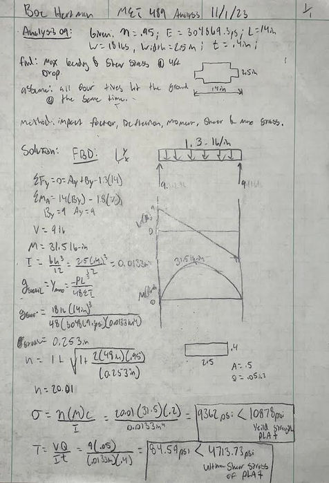
Analysis 04 was used to determine if the RC Baja Car would pass requirement 1.d.2 requiring the vehicle to survive a four foot drop. This was performed using equilibrium equations to find the max moment of 31.5 lbs and a max shear of 9 lbs. Along with finding the deflection 0.25 inches. Which was used to find the impact factor associated with the four foot drop. The impact factor was found to be 20. This was used to find the max stress and max shear stress the RC Car would experience from the four foot drop. The max stress was 9362psi vs 10878psi for the yield strength of PLA+. The max shear stress found to be 84.5psi vs 4714psi for the ultimate shear stress of PLA+
Image 2.4 - Analysis 04
Analysis 05 - Minimum Chassis Thickness
Analysis 05 was used to determine if the RC Baja Car would pass requirement 1.d.15 requiring the vehicle to not deflect more than 5/16 of an inch under an 18 lbs load. This was performed using deflection equations for a three point load, then solving for the thickness. It was determined the minimum thickness for PLA+ should be 0.325in.

Image 2.5 - Analysis 05

Analysis 06 - Minimum Chassis Thickness Utilizing 65D Material
Analysis 06 was used to determine if the RC Baja Car would pass requirement 1.d.15 requiring the vehicle to not deflect more than 5/16 of an inch under an 18 lbs load. This was performed using deflection equations for a three point load, then solving for the thickness. Utilizing the young's modulus for 65D found through testing. It was determined the minimum thickness for 65D should be 3.36 in, which is far to thick to realistically be used on the chassis.
Image 2.6 - Analysis 06